 2a78f1b609
Dashboard (web/hand_web.py)
- Record/replay panel driving g1_record_replay.py as a pty child: take library
  (replay/download/duplicate/rename/delete/upload/delete-all), pause & resume,
  and in-take key buttons that grey out in the --fingers modes the recorder
  ignores (measured: in touch mode the keys change nothing at all).
- /api/restart is container-aware: it kills inspire_g1 and lets the supervisor
  relaunch it. It used to run manage.sh, which started a SECOND inspire_g1
  beside the supervised one - two writers on one RS-485 bus - and never
  returned.
- Shape/combo libraries take a .bak on every write, with an undo button. Both
  files are rewritten in full, so deleting the last entry was unrecoverable.

recorder/
- The recorder lives in this project now: one source of truth for the CLI and
  the dashboard, with pause/resume added to replay.
- record.sh picks a runtime by itself (a python with the SDK, the vendored SDK,
  or the inspire-hand container). bundle.sh packs a ~340KB portable kit.

tools/
- preflight.sh: read-only readiness report for a new robot (hardware, docker,
  build prerequisites, per-robot settings) ending in an install-path verdict.
- fetch_deps.sh: stage build dependencies, verifying the libs are aarch64.
- export_ui.py: regenerate an embedding app's vendored copy of the UI.

docker/
- build_image.sh resolves its dependencies from several layouts: deps/ inside
  the project, /usr/local, a source install prefix, or a ROS2 colcon workspace
  (where the idl headers live when /usr/local has none).
- web/ is copied in the last layer, so dashboard edits skip the C++ rebuild.
- restart=always, and start.sh always builds so an edit cannot silently run a
  stale image.

deps/unitree_sdk2 is vendored so a robot that has never seen the SDK can build.
Docs: README quickstart + embedding notes, SETUP_G1 corrected (that udev rule
stopped creating /dev/inspire_* symlinks a while ago), ROBOT_README describing
a live install.
5.1 KiB
5.1 KiB
Unitree H1_2 并联机构控制
English | 简体中文
并联机构控制接口
Unitree H1_2 机器人并联机构涉及机器人的左右腿的脚踝。因左右脚踝对称,故下面以 H1_2 左脚踝关节为例:
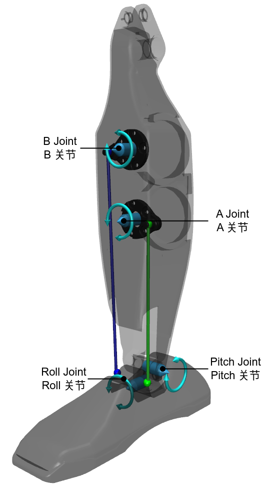
硬件上,H1_2 左脚踝关节采用并联机构,包括四个关节:
- 并联关节:A 关节、B 关节
- 串联关节:Pitch 关节 (简称 P 关节)、Roll 关节 (简称 R 关)
其中只有 A、B 关节是可被电机直接驱动的关节,P、R 关节不能被直接控制。而机器人 URDF 模型和运动控制算法通常只考虑 P、R 串联关节。为了实现对 P、R 关节的控制,我们通过控制 A、B 关节从而间接实现对 P、R 关节的控制。具体到软件上,我们为用户提供了等价的串联关节控制接口,即 PR 模式,让用户能直接控制 P、R 关节。与普通关节控制方法一样,PR 模式 下每个串联关节接收以下指令:
| 指令名称 | 变量 |
|---|---|
| 前馈力矩 | tau |
| 目标角度 | q |
| 目标角速度 | dq |
| 关节刚度 | kp |
| 关节阻尼 | kd |
最终串联关节执行总的力矩为 T = kp * (q - q_m) + kd * (dq - dq_m) + tau。为了提高串联关节控制精度,H1_2 机器人内部根据运动学和动力学关系,把 P、R 关节的前馈力矩、目标角度、目标角速度、关节刚度和关节阻尼指令转换为 A、B 实际关节执行单元。
串联关节跟踪实验
为测试 H1_2 脚踝 PR 模式 控制效果,我们让脚踝 P、R 关节跟踪正弦曲线,参考测试例程。核心代码段如下:
启用 PR 模式并生成正弦曲线
// [Stage 2]: swing ankle's PR
mode_ = PR;  // Enable PR mode
// generate sin/cos trajectory
double max_P = 0.25;  // [rad]
double max_R = 0.25;  // [rad]
double t = time_ - duration_;
double L_P_des = max_P * std::cos(2.0 * M_PI * t);
double L_R_des = max_R * std::sin(2.0 * M_PI * t);
double R_P_des = max_P * std::cos(2.0 * M_PI * t);
double R_R_des = -max_R * std::sin(2.0 * M_PI * t);
设置踝关节指令
// update ankle joint position targets
float Kp_Pitch = 80;
float Kd_Pitch = 1;
float Kp_Roll = 80;
float Kd_Roll = 1;
dds_low_command.motor_cmd().at(4).q() = L_P_des;  // 4: LeftAnklePitch
dds_low_command.motor_cmd().at(4).dq() = 0;
dds_low_command.motor_cmd().at(4).kp() = Kp_Pitch;
dds_low_command.motor_cmd().at(4).kd() = Kd_Pitch;
dds_low_command.motor_cmd().at(4).tau() = 0;
dds_low_command.motor_cmd().at(5).q() = L_R_des;  // 5: LeftAnkleRoll
dds_low_command.motor_cmd().at(5).dq() = 0;
dds_low_command.motor_cmd().at(5).kp() = Kp_Roll;
dds_low_command.motor_cmd().at(5).kd() = Kd_Roll;
dds_low_command.motor_cmd().at(5).tau() = 0;
dds_low_command.motor_cmd().at(10).q() = R_P_des;  // 10: RightAnklePitch
dds_low_command.motor_cmd().at(10).dq() = 0;
dds_low_command.motor_cmd().at(10).kp() = Kp_Pitch;
dds_low_command.motor_cmd().at(10).kd() = Kd_Pitch;
dds_low_command.motor_cmd().at(10).tau() = 0;
dds_low_command.motor_cmd().at(11).q() = R_R_des;  // 11: RightAnkleRoll
dds_low_command.motor_cmd().at(11).dq() = 0;
dds_low_command.motor_cmd().at(11).kp() = Kp_Roll;
dds_low_command.motor_cmd().at(11).kd() = Kd_Roll;
dds_low_command.motor_cmd().at(11).tau() = 0;
打印期望值和测量值到终端
float L_P_m = low_state_.motor_state().at(4).q();
float L_R_m = low_state_.motor_state().at(5).q();
float R_P_m = low_state_.motor_state().at(10).q();
float R_R_m = low_state_.motor_state().at(11).q();
printf("%f,%f,%f,%f,%f,%f,%f,%f\n", L_P_des, L_P_m, L_R_des, L_R_m, R_P_des, R_P_m, R_R_des, R_R_m);
| L_P_des | L_P_m | L_R_des | L_R_m | R_P_des | R_P_m | R_R_des | R_R_m |
|---|---|---|---|---|---|---|---|
| 左脚 Pitch 期望值 | 左脚 Pitch 测量值 | 左脚 Roll 期望值 | 左脚 Roll 测量值 | 右脚 Pitch 期望值 | 右脚 Pitch 测量值 | 右脚 Roll 期望值 | 右脚 Roll 测量值 |
安装并编译 unitree_sdk2,务必先把机器人悬挂起来,然后终端运行测试例程:
h1_2_ankle_track network_interface
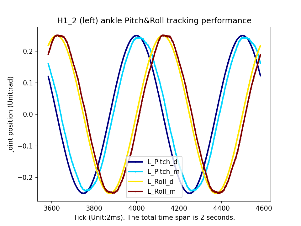
启动后,机器人会先恢复到零位,然后周期性摆动脚踝,并打印左右踝关节期望值和测量值,其位置跟踪效果如图:
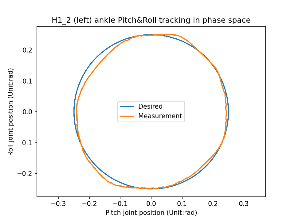
图中符号定义:
L_Pitch_d:左脚踝 P 关节期望值L_Pitch_m:左脚踝 P 关节测量值L_Roll_d:左脚踝 R 关节期望值L_Roll_m:左脚踝 R 关节测量值
左图表示串联 Pitch、Roll 关节能较准确地跟踪正弦曲线目标位置指令;右图表示串联关节在相空间中的跟踪效果。